Sign In
 Create Account


http://www.carcraft.com/howto/91758/
QUOTE
How To Set Pinion Angle
Ask 10 Guys About Optimal Pinion Angle And A Lively Debate Will Ensue
By Marko Radielovic
Pinion angle simply refers to the angle of the differential’s pinion in relation to the driveshaft. But ask 10 guys about optimal pinion angle and a lively debate will ensue. To get a range of opinions, we spoke to several well-known and respected chassis builders about pinion angles. While their recommendations differ somewhat, they all agree on some basic principals. We’ll give you their take on the subject, and show you the various ways to measure and correct this very important aspect of chassis tuning.
Optimum Pinion Angle
Due to the dynamic nature of an automobile chassis, the various angles and symmetries are constantly changing, which adds to the complexity of obtaining driveline nirvana. Furthermore, we live in the real world where time takes its toll on our automobiles. Engines may not sit squarely in their motor mounts, motor mounts may not sit properly between the framerails, crossmembers may not sit straight, and who knows where the rearend is positioned (ours is usually in a chair behind a desk). Despite all these factors affecting the positioning of our drivetrains, they seem to work well enough in most cases, at least on the street in basically stock applications. We owe this functionality to the universal joint, which, by design, corrects for slight misalignments between the driving components (crankshaft and transmission) and the driven components (driveshaft and differential) of the drivetrain.
Pro Stock chassis builder Jerry Bickel assures us, “there is no mystery to pinion angle.” Setting the pinion angle is the final step in driveline alignment. The goal is to create a straight line from the back of the crankshaft through the transmission, driveshaft, and the pinion of the differential—under load. Due to the tendency of the pinion to rise under load, some angle must be present at rest.
How well the rear suspension controls the position of the rearend is the most critical issue that determines how much pinion angle will be needed. Some types of rear suspensions offer more control than others and require different angles. According to Bickel, a ladder-bar suspension normally requires ½ degree of pinion angle, a four-link requires 1-2½ degrees, and a leaf-spring suspension requires up to 6 to 7 degrees. In all examples, we’re talking about negative pinion angle, i.e., the pinion is nose-down in relation to the driveshaft. Bickel says a straight driveline delivers the most power to the rear wheels. For more on race car chassis tuning, Bickel offers classes as well as detailed books on the topic.
Ray Currie of Currie Enterprises, which specializes in rearends and rear suspension systems for race, street, and off-road applications, agrees that pinion angle is a pretty simple (there’s that word again) concept. He explains that a universal joint is designed to handle between 1 and 3 degrees of pinion angle. This is a safe operating range for the U-joint. If the U-joint is forced beyond its normal range, it can hyperextend and lead to catastrophic failure. Currie always strives for 2 degrees of pinion angle on a street car regardless of the type of rear suspension being used.
With a leaf spring–equipped car, the differential movement isn’t nearly as controlled as that of a four-link suspension, so more angle may be needed to prevent the U-joint from hyperextending beyond zero degrees under load. Sometimes people increase the pinion angle to increase dragstrip bite, but Currie does not recommend this approach for a street car. Currie says “ideal is ideal,” and the correct pinion angle should be incorporated in the part-time as well as the full-time race car.
Suspension specialist Dick Miller bases pinion angle settings on horsepower. Miller likes to see 2 degrees of negative pinion angle (relative to the driveshaft) on applications in the 400hp range, 3½ to 4½ degrees in the 500hp to 650hp range, and up to 7 degrees with 700 horses or more. Miller also acknowledges that the greater the pinion angle, the more horsepower the driveline will consume, but it’s a compromise that must be made. Miller notes that these angles are merely guidelines, and each individual combination should be fine-tuned.
Setting Pinion Angle
We paid a visit to Currie’s shop in Anaheim, California, home of Mickey Mouse and the Magic Kingdom, to observe the method he uses to measure pinion angle. Currie takes the process one step further by factoring in the transmission output shaft’s angle in determining where the pinion angle should be set.
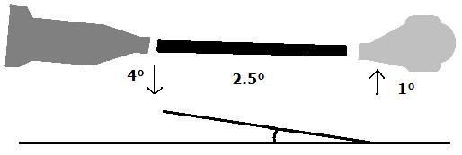
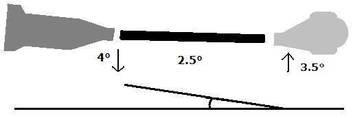
Sometimes corrections need to be made at the front of the vehicle to ensure that the engine and trans are sitting in the proper location. According to Currie, the average car crafter should strive for between 1 and 3 degrees between the tailshaft of the transmission and driveshaft, and 1 to 3 degrees between the driveshaft and pinion. Furthermore, the two angles should be nearly equal (between 1 and 3 degrees), but always opposite (see crude diagram).
Probably the two most common rear-suspension configurations to come out of Detroit on musclecars are the four-link and leaf-spring suspensions. On four-link–equipped automobiles, adjustable upper control arms are required to change the pinion angle (although in some cases, mild adjustments can be made by shimming the transmission mount). This is made possible by adjustable upper control arms from a number of aftermarket sources, including Dick Miller, Hotchkis, and Edelbrock. In the case of a leaf spring–equipped car, pinion angle is changed with angled wedges (shims) that are placed between the leaf spring and the shock-absorber mount (see photo). These wedges effectively rotate the differential forward or backwards depending on which way the wedge is facing.
Whether it’s for a 16-second daily driver or an 8-second door-slammer, the proper pinion angle is vital for delivering power safely and effectively to the rear wheels.
Ask 10 Guys About Optimal Pinion Angle And A Lively Debate Will Ensue
By Marko Radielovic
Pinion angle simply refers to the angle of the differential’s pinion in relation to the driveshaft. But ask 10 guys about optimal pinion angle and a lively debate will ensue. To get a range of opinions, we spoke to several well-known and respected chassis builders about pinion angles. While their recommendations differ somewhat, they all agree on some basic principals. We’ll give you their take on the subject, and show you the various ways to measure and correct this very important aspect of chassis tuning.
Optimum Pinion Angle
Due to the dynamic nature of an automobile chassis, the various angles and symmetries are constantly changing, which adds to the complexity of obtaining driveline nirvana. Furthermore, we live in the real world where time takes its toll on our automobiles. Engines may not sit squarely in their motor mounts, motor mounts may not sit properly between the framerails, crossmembers may not sit straight, and who knows where the rearend is positioned (ours is usually in a chair behind a desk). Despite all these factors affecting the positioning of our drivetrains, they seem to work well enough in most cases, at least on the street in basically stock applications. We owe this functionality to the universal joint, which, by design, corrects for slight misalignments between the driving components (crankshaft and transmission) and the driven components (driveshaft and differential) of the drivetrain.
Pro Stock chassis builder Jerry Bickel assures us, “there is no mystery to pinion angle.” Setting the pinion angle is the final step in driveline alignment. The goal is to create a straight line from the back of the crankshaft through the transmission, driveshaft, and the pinion of the differential—under load. Due to the tendency of the pinion to rise under load, some angle must be present at rest.
How well the rear suspension controls the position of the rearend is the most critical issue that determines how much pinion angle will be needed. Some types of rear suspensions offer more control than others and require different angles. According to Bickel, a ladder-bar suspension normally requires ½ degree of pinion angle, a four-link requires 1-2½ degrees, and a leaf-spring suspension requires up to 6 to 7 degrees. In all examples, we’re talking about negative pinion angle, i.e., the pinion is nose-down in relation to the driveshaft. Bickel says a straight driveline delivers the most power to the rear wheels. For more on race car chassis tuning, Bickel offers classes as well as detailed books on the topic.
Ray Currie of Currie Enterprises, which specializes in rearends and rear suspension systems for race, street, and off-road applications, agrees that pinion angle is a pretty simple (there’s that word again) concept. He explains that a universal joint is designed to handle between 1 and 3 degrees of pinion angle. This is a safe operating range for the U-joint. If the U-joint is forced beyond its normal range, it can hyperextend and lead to catastrophic failure. Currie always strives for 2 degrees of pinion angle on a street car regardless of the type of rear suspension being used.
With a leaf spring–equipped car, the differential movement isn’t nearly as controlled as that of a four-link suspension, so more angle may be needed to prevent the U-joint from hyperextending beyond zero degrees under load. Sometimes people increase the pinion angle to increase dragstrip bite, but Currie does not recommend this approach for a street car. Currie says “ideal is ideal,” and the correct pinion angle should be incorporated in the part-time as well as the full-time race car.
Suspension specialist Dick Miller bases pinion angle settings on horsepower. Miller likes to see 2 degrees of negative pinion angle (relative to the driveshaft) on applications in the 400hp range, 3½ to 4½ degrees in the 500hp to 650hp range, and up to 7 degrees with 700 horses or more. Miller also acknowledges that the greater the pinion angle, the more horsepower the driveline will consume, but it’s a compromise that must be made. Miller notes that these angles are merely guidelines, and each individual combination should be fine-tuned.
Setting Pinion Angle
We paid a visit to Currie’s shop in Anaheim, California, home of Mickey Mouse and the Magic Kingdom, to observe the method he uses to measure pinion angle. Currie takes the process one step further by factoring in the transmission output shaft’s angle in determining where the pinion angle should be set.
Sometimes corrections need to be made at the front of the vehicle to ensure that the engine and trans are sitting in the proper location. According to Currie, the average car crafter should strive for between 1 and 3 degrees between the tailshaft of the transmission and driveshaft, and 1 to 3 degrees between the driveshaft and pinion. Furthermore, the two angles should be nearly equal (between 1 and 3 degrees), but always opposite (see crude diagram).
Probably the two most common rear-suspension configurations to come out of Detroit on musclecars are the four-link and leaf-spring suspensions. On four-link–equipped automobiles, adjustable upper control arms are required to change the pinion angle (although in some cases, mild adjustments can be made by shimming the transmission mount). This is made possible by adjustable upper control arms from a number of aftermarket sources, including Dick Miller, Hotchkis, and Edelbrock. In the case of a leaf spring–equipped car, pinion angle is changed with angled wedges (shims) that are placed between the leaf spring and the shock-absorber mount (see photo). These wedges effectively rotate the differential forward or backwards depending on which way the wedge is facing.
Whether it’s for a 16-second daily driver or an 8-second door-slammer, the proper pinion angle is vital for delivering power safely and effectively to the rear wheels.
 Back to top